


Control your Boost
Turbocharged engines rely one of a few different methods of controlling the boost level. Most modern-day gasoline engines rely on a “wastegate”, while diesel engines generally rely on Variable Geometry Turbochargers (VGT). In both cases, boost pressure and airflow is the result of engine exhaust gasses passing through the turbine of the turbocharger, of which the compressor shares a common shaft. Hence, turbine acceleration causes compressor acceleration which causes boost pressure and airflow to rise. With a wastegated turbocharger, the turbine and compressor speed are controlled by allowing a variable amount of engine exhaust gasses to bypass the turbine. With a VGT, the angle and shape of the turbine vanes can be changed on the fly, which affects the speed of both the turbine and compressor. VGTs are considered to be more efficient as the turbocharger's mechanical characteristics can effectively be changed, on the fly.
(As an aside, the reason VGTs aren't prevalent on gasoline engines is because the exhaust temperatures tend to be much higher, although materials technology has caught up and VGTs are slowly making their way into high end gasoline engined vehicles like the Koenigsegg One:1)
Wastegated Turbochargers
The remainder of this article will focus on wastegated turbochargers (specifically internally wastegated turbochargers), since that is the type that is used in on the 1.4L turbocharged engine. In the age before Electronic Control Unit (ECU) controlled engines, the original wastegated turbochargers used a purely mechanical approach to controlling the boost. A calibrated “wastegate actuator” (WGA) would use spring pressure to hold the wastegate “default-closed”. Exhaust pressure levels “pre-turbine” (in other words, the exhaust pressure between the exhaust port and the “front side” of the turbine) rise in accordance with boost levels, and once there is sufficient pressure on the wastegate to overcome the spring weight in the WGA (sometimes called the cracking pressure), the wastegate will start to open and allow exhaust to bypass the turbine. This regulates boost pressure and airflow.
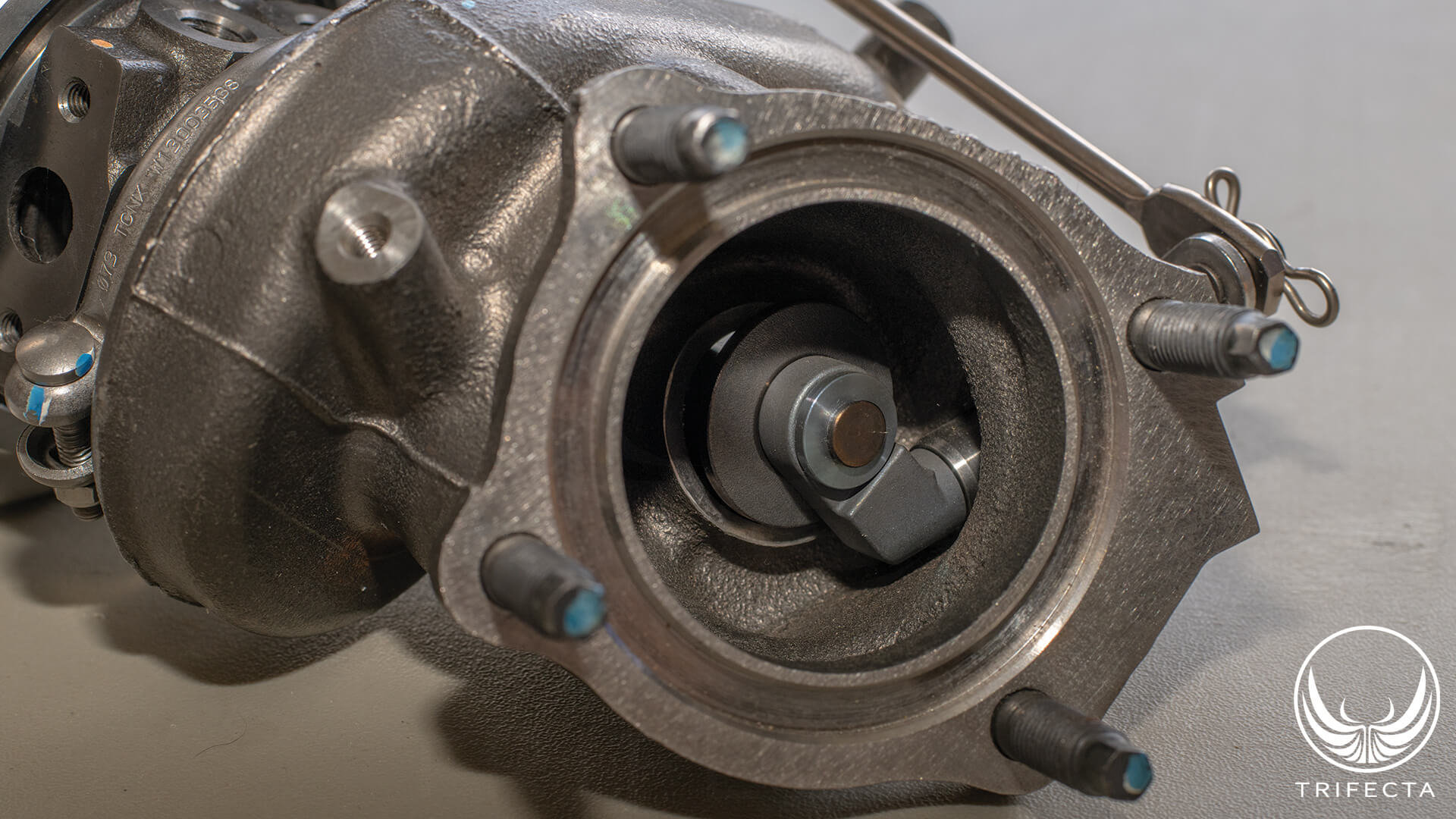
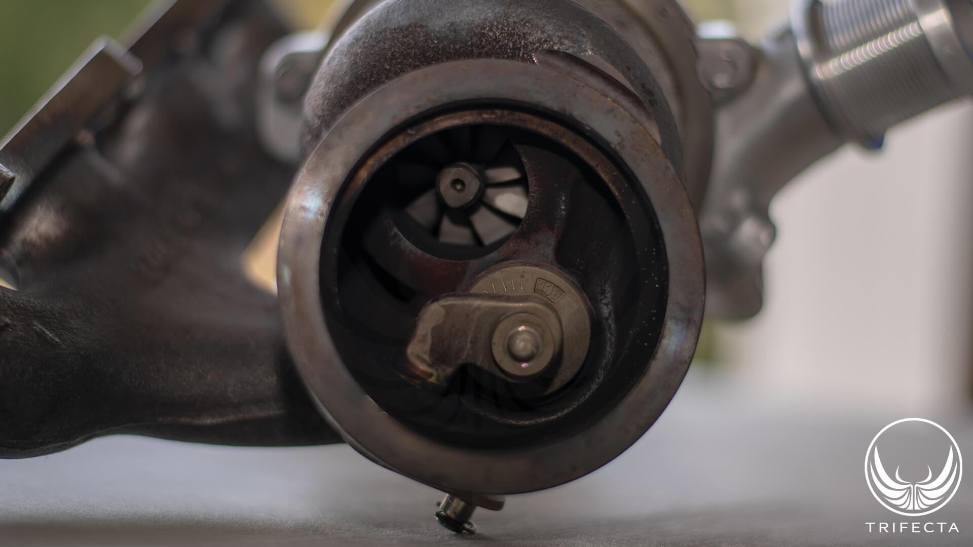 LUJ/LUV Turbocharger turbine and internal wastegate (wastegate closed)
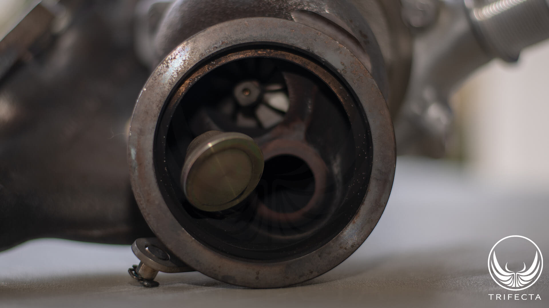 LUJ/LUV Turbocharger turbine and internal wastegate (wastegate open)
In the age of purely mechanical wastegates, it was relatively easy to increase boost levels beyond OE design specifications – all one had to do is install a heavier spring in the WGA, and the cracking pressure would increase, which would cause the turbine to spin faster, which in turn would cause the compressor to spin faster and compress more air. Of course, fueling and ignition advance curves would have to be modified, not to mention charge cooling systems as increasing the boost would also increase the amount of heat generated from compressing the incoming air.
ECU Control – A Twist on Mechanical Wastegates
When ECUs started managing engine operation, engineers had to come up with a method that would allow the boost to be regulated electronically, and, additionally through a closed-loop feedback system that would allow the ECU to compensate for changes in environment (air temperature, altitude, fuel quality) as well as changes to the engine operation as it wore mechanically. The earliest turbocharged engines from General Motors utilized a similar WGA as was from the mechanical days, with a twist: the addition of a pressure reference port which could effectively lower the WGA cracking pressure by applying pressurized air.
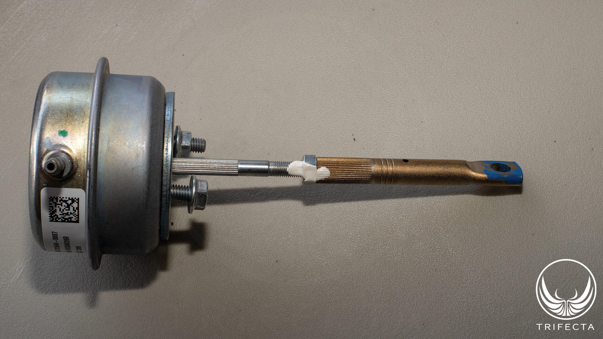 LUJ/LUV Wastegate Actuator (WGA)
In this system, there is also a boost control solenoid (BCS) which is essentially like an electronic diverter valve. By providing a Pulse Width Modulated (PWM) signal from the ECU, the ECU can control how much of the boost pressure coming from the compressor is allowed to be directed to the WGA. On General Motors vehicles, the usable PWM duty cycle range is 5% to 95%, where 5% causes the maximum amount of boost pressure to be directed to WGA, and 95% causes minimal amount of the boost pressure to be directed to the WGA. In other words, when the BCS command is 5%, the lowest amount of boost will be produced, and when it is 95%, the highest amount of boost will be produced. The following pictures show the BCS on the LUJ/LUV engine:
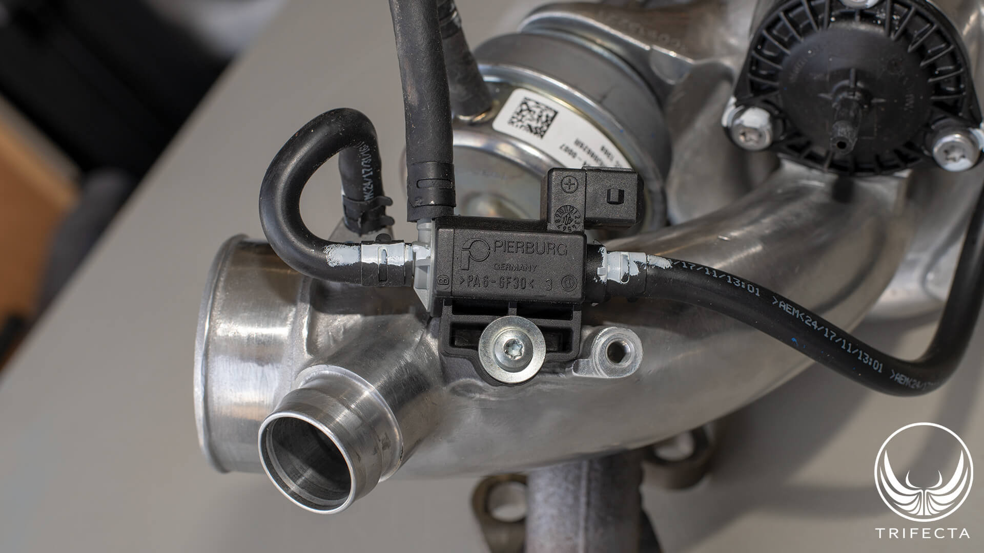 LUJ/LUV Boost Control Solenoid (BCS)
The ECU determines the “desired boost” level based on myriad decision inputs, including calibrated power limits, calibrated powertrain component limits (e.g. maximum turbocharger compressor speed), driver power demand, altitude, incoming air temperature, amount of historical knock, just to name a few. Once the ECU makes a decision on the boost level, it references a calibrated table to decide how much duty cycle should be output to the BCS, and drives (commands) the BCS to that duty cycle.
The ECU then monitors incoming air mass via the Mass Air Flow (MAF) sensor, the intake Manifold Absolute Pressure (MAP) sensor, the Throttle Inlet Absolute Pressure (TIAP, or “boost”) sensor, and several Intake Air Temperature (IAT) sensors to determine if the turbocharger is operating as desired. If the actual boost level is lower than the desired boost level, this is considered an “underboost” condition and the ECU will make some dynamic increases to the BCS signal to try to correct the condition. If the actual boost level is higher than the desired boost level, this is considered an “overboost” condition and the ECU will dynamically reduce the BCS signal to try to correct the condition. In an overboost condition, it may take further, more drastic measures depending on the severity of the condition such as shutting down boost entirely, closing the throttle blade, or opening the bypass valve. This is done to protect the engine and its components (more on these conditions later).
The ECU employs a Proportional-Integral-Derivative controller (PID controller) strategy to both immediately correct boost control errors, and also correct predicted future boost control errors. This is the “closed loop” portion of the system. The parameters of this system are part of the ECU calibration and can be modified as needed. This article won't go into depth regarding how a PID controller works, but there's a great reference on Wikipedia (https://en.wikipedia.org/wiki/PID_controller) that describes both the method and the mathematics behind it.
Advancements in ECU Turbocharger Controls
Since the original boost control system design on General Motor vehicles, two variants have come along. The first is used on the twin turbo V6 engines (RPO: LF3, LF4 and LGW). The system works very similarly to the “default closed” systems originally used, but in this case, the wastegates are “default open”. Mechanical spring pressure holds the wastegate open until boost is required. The advantage with this system is it allows for more efficient engine operation. If you consider the “default closed” system design, one drawback is the exhaust gasses are ALWAYS flowing through the turbine. Even under light duty, even where no boost is requested by the ECU, the exhaust still flows through the turbine, and the turbine still acts as an exhaust restriction, which reduces efficiency. The only way the wastegate can be opened is for the mechanical spring pressure to be exceeded, which can only happen when there's sufficient boost.
The “default open” design aims to resolve this shortcoming. Instead of using positive pressure (boost) to control the WGA, negative pressure (vacuum) is used. When the WGA is subjected to atmospheric pressure, the wastegate is fully open. As the pressure supplied to the WGA drops, it starts to pull against a spring inside the WGA to close the wastegate. The negative pressure is generated by a mechanical pump driven by an engine component, and is controlled using a BCS which directs a controlled amount of vacuum to the WGA. It is essentially the inverse of the “default closed” system design.
LF3 turbocharger with “default open” wastegate design
This system is not without its drawbacks, however. It's significantly more complicated than the “default closed” system design because it relies on a system of vacuum pumps, lines and solenoids to control the turbocharger. Another interesting issue that has arisen on this system is the turbochargers can be noisy. The wastegate valve itself is a floating valve attached to the wastegate actuator arm. When the wastegates are open, they have a tendency to create an annoying rattling sound, and because the aim of the design was to keep the wastegates open under low power levels and at idle, the sound can be easily heard. General Motors even revised the turbocharger assembly several times in order to correct the problem. This cannot be an issue on “default closed” systems because the wastegate valve would be held against the wastegate orifice under these light load and idle conditions.
But, on the very newest turbocharged engines General Motors is producing, such as the new 2.0L turbocharged engine (RPO:LSY), its larger 2.7L cousin (RPO: L3B), and the new 4.2L twin turbo V8 engine (RPO: LTA a.k.a. “Blackwing”), there's an exciting new technology being used! Doing away entirely with all of the pressure-based controls, the ECU now simply drives what is essentially the equivalent of a throttle blade actuator which directly drives the wastegate position. It also uses the “default open” design to improve efficiency. The aftermarket has not yet delved into calibrating any of these engines, so little is known about how effective this new solution is.
Limitations with the Gen 1 1.4L Turbo Engine Wastegate System
Now, we will discuss the specific issues with the LUJ/LUV engine turbocharger's wastegate system. The main issue we have observed is there can be quite a variance in the cracking pressure of the OE WGA assembly. Based on our years of experience in calibrating these vehicles, we can say that on average, a safe assumption is that the highest boost level that can be had on the OE WGA assembly, at sea level is around 20-22psi of boost. However, we've have also seen OE WGA assemblies that will support more than 25-26psi of boost. Our assumption is that because these vehicles, in stock form were never designed to make these kinds of boost levels, perhaps the manufacturing tolerances in the OE WGA is somewhat lax.
When calibrating customer vehicles, however, we have to start with the lowest common demoninator or else our customers could end up with boost control diagnostic failures and subsequent “boost limp mode”.
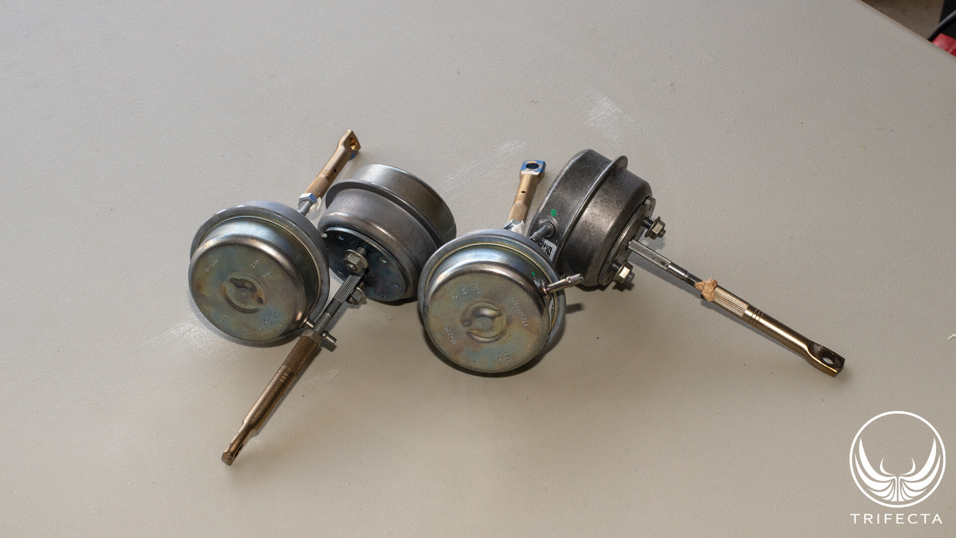 Collection of LUJ/LUV WGAs that all have different cracking pressures
Adjusting OE WGA “Preload” a.k.a. “Playing With Fire”
One of the classic (or perhaps “infamous”) techniques for changing boost levels (particularly before boost levels were managed by an ECU) was to adjust the length of the rod from the WGA to the wastegate arm. The original intent of using an adjustable rod length was to allow calibration of the wastegate but hot-rodders quickly figured out if they shortened the length of the rod, they could either restrict the amount the wastegate could open, or otherwise cause the cracking pressure to go higher (because of the additional preload on the spring).
On the LUJ/LUV engine, indeed an adjustable length threaded rod is used between the WGA and the wastegate, but the factory attempts to prevent tampering by using some sort of locking compound on the threads. This isn't enough to stop a dedicated tinkerer, but we wholly recommend AGAINST modifying the length of this arm for the simple reason that it can cause the turbocharger to overspin which leads to either a failed turbocharger assembly, or a failed engine.
LUJ/LUV WGA showing tamper-resistent compound on actuator arm adjustment
Additionally, changing the WGA rod length will have no effect on the boost potential without corresponding tuning changes because the ECU will detect there's more boost than expected and simply respond by either commanding less BCS duty cycle, or closing the throttle.
Introducing the Forge Billet WGA for the LUJ/LUV
Forge is an aftermarket UK company that specializes in engineering and manufacturing aftermarket WGAs (among many other parts). They have developed a billet aluminum WGA for the LUJ/LUV engine (Forge part number FMACC14T). One of the fascinating features of their part is the mechanical cracking pressure can be adjusted through the use of interchangible springs. Through our testing process, we found their part to be incredibly consistent from unit to unit (unlike the OE WGA) and of high quality.
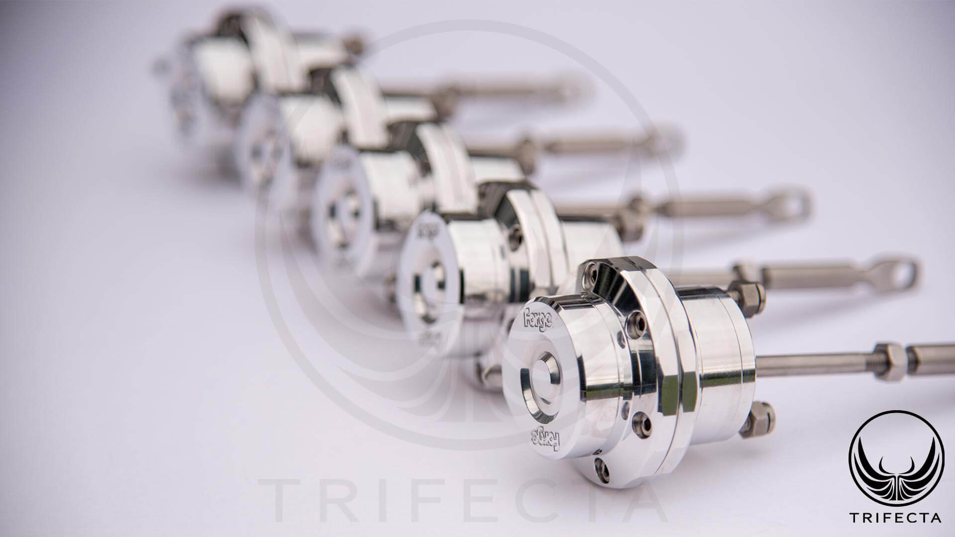
Forge Motorsport FMACC14T w/ “Yellow” spring pre-installed
When you purchase this WGA from Forge, off the shelf it includes a “green” spring pre-installed in the WGA. We found this spring to be too “light” - in other words, the cracking pressure was actually LOWER than the OE WGA. We tested the next heavier spring, which is the “yellow” spring, and found it to be a suitable choice for the LUJ/LUV in that it allows boost pressures to reach the potential of the engine and OE turbocharger closely.
We could have, of course, chosen an even heavier spring (such as the “red” spring). However, there is a trade-off using a heavier spring that needs to be recognized. Not only does the heavier spring weight raise the cracking pressure of the wastegate (e.g. the MAXIMUM potential boost level), but it also, in effect, raises the MINIMUM pressure that can be made from the turbocharger when 100% of the pressure is being sent to the WGA (e.g. 5% duty cycle). The OE WGA has a minimum of around 5psi of boost, but the Forge WGA with the “yellow” spring is closer to 12psi.
We chose the “yellow” spring because it's the lightest spring that can allow the maximum boost potential to be reached which in turn raises the mininum boost by the lowest amount possible. If the minimum boost level is raised too far, it can cause a clunky driving experience, because the ECU will have to manage the torque by closing the throttle blade instead of being able to open the wastegate.
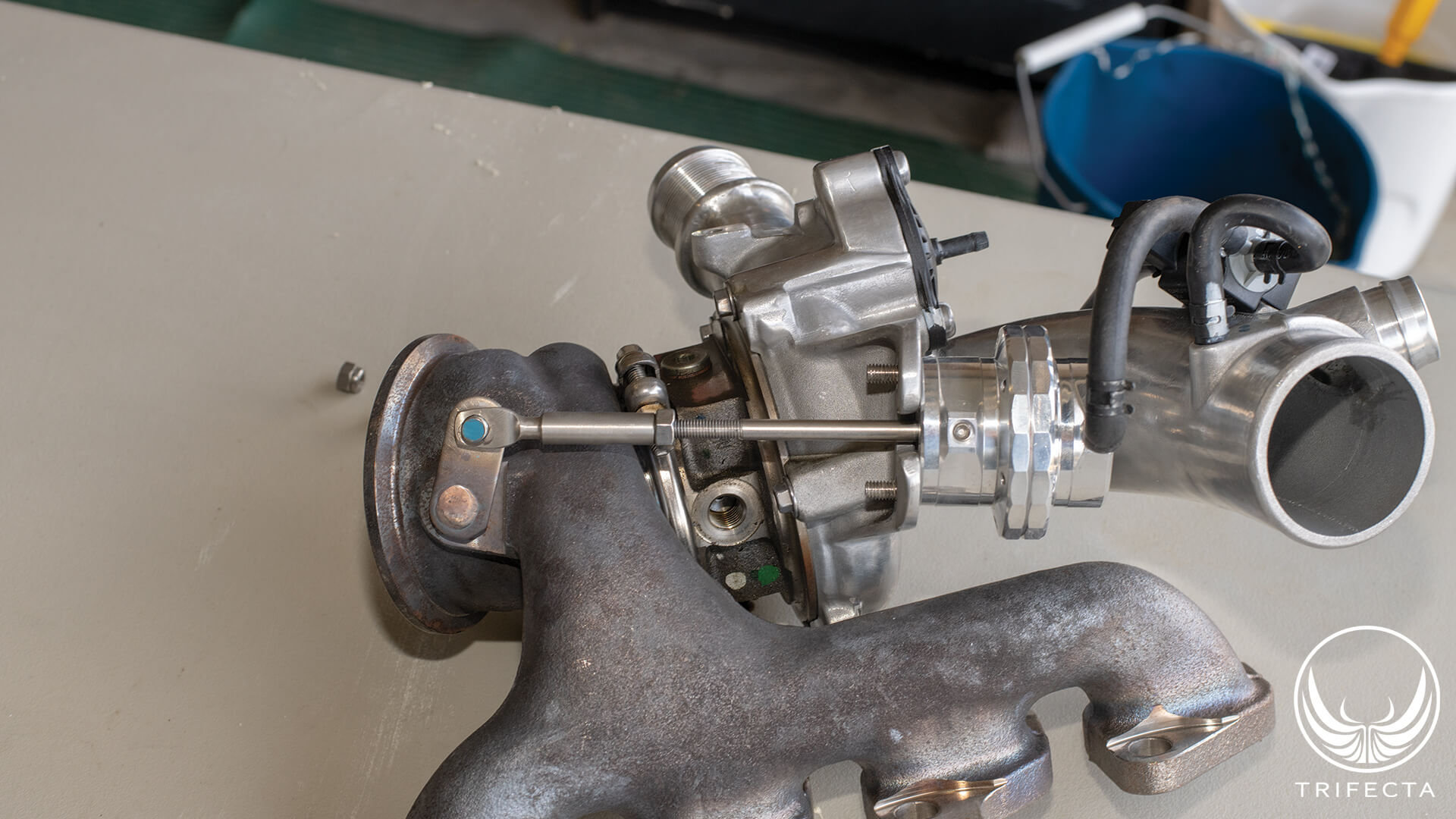
Forge Motorsport WGA installed on LUJ/LUV turbocharger
So, what about the power?
We recently performed a series of tests on one of our development vehicles. It is a 2016 Chevrolet Sonic LT, with the LUV engine, and a manual transmission. It has the following modifications:
- 60 lb/hr fuel injectors
- RacerX cold air intake
- SPEC billet aluminum flywheel
- WaveTrac Limited Slip Differential (LSD)
- TRIFECTA calibration
Out of the LUJ/LUV vehicles we have at our disposal, this one was closest to stock configuration, and the few modifications it does have would not materially affect the power output, except for perhaps the flywheel. As expected, on the stock calibration (adjusted for the 60 lb/hr fuel injectors), this vehicle baselined at fairly high numbers on our dyno:
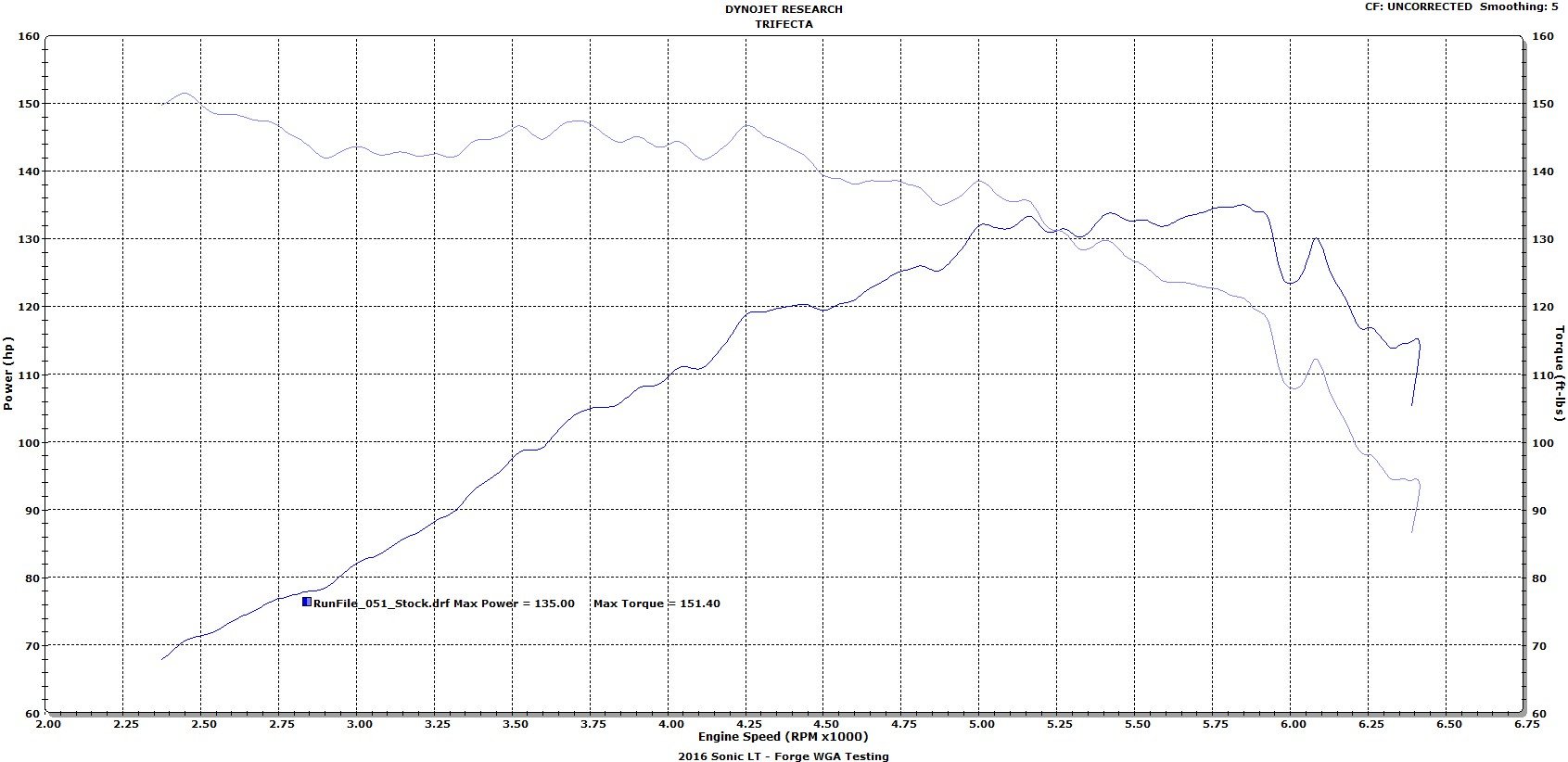
Peak power output was 135 horsepower (HP) at the wheels (WHP), and 151 lb-ft torque (TQ) at the wheels (WTQ). Considering this vehicle is rated at 139HP / 149TQ at the flywheel from the factory, it would seem indeed the aluminum flywheel had a positive impact on power output for this vehicle.
TRIFECTA Calibration with the OE WGA
As started above, we consider 22psi (at sea level) to be the highest boost level that can be achieved on the OE WGA. This dyno chart shows what 22psi on this vehicle produced versus the OE calibration:
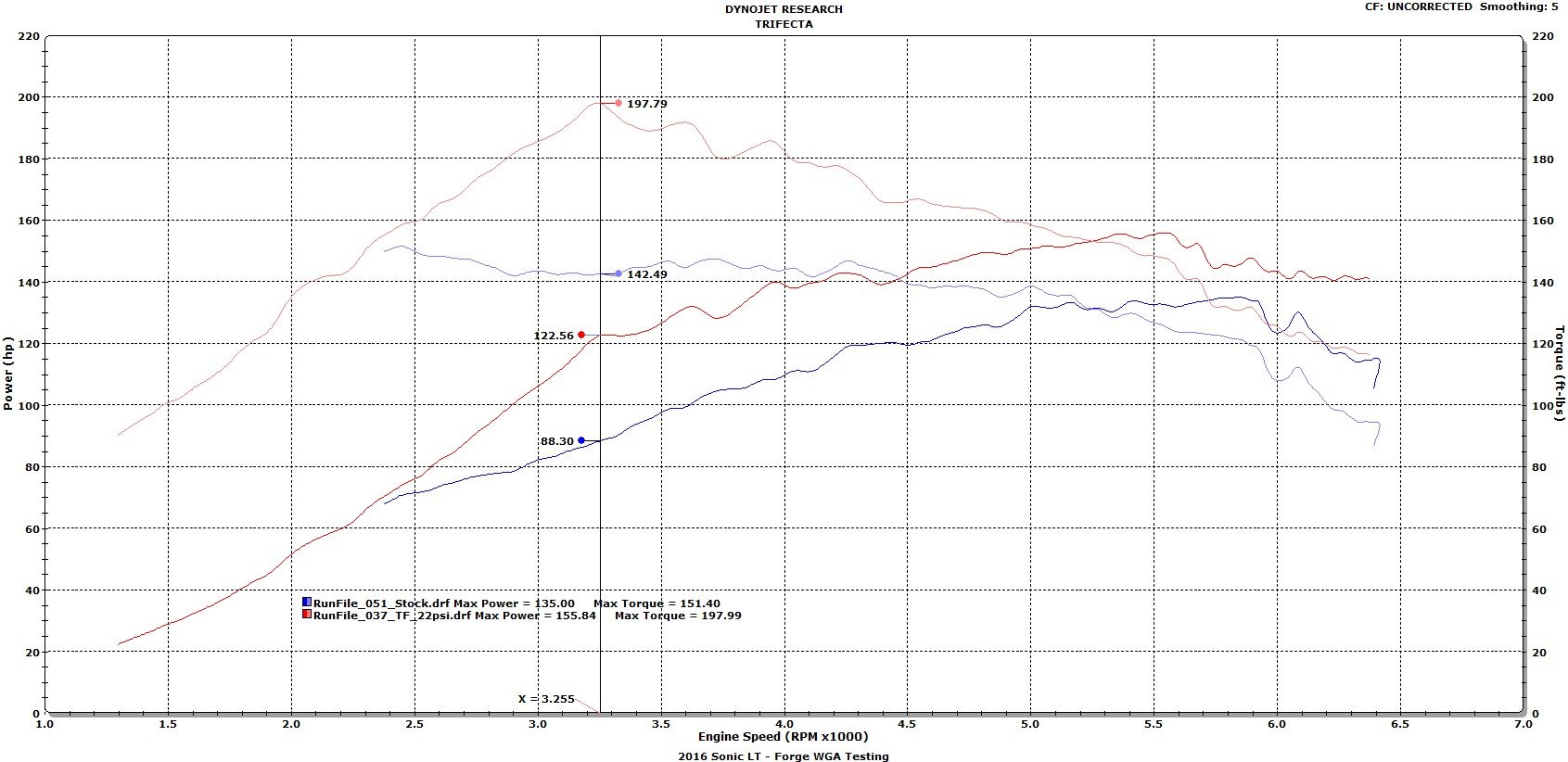
Under these test conditions, PEAK gains went up by approximately 26WHP and 47WTQ. However, particularly with horsepower levels after the curve, gains are much higher than 26WHP – e.g. at 6300 RPM, the gains are closer to 45WHP. High RPM power delivery holds much further into the high RPM range than on the OE calibration.
TRIFECTA Calibration with the Forge WGA and “Yellow” Spring
Finally, we tested the vehicle and calibrated it to its full potential with the Forge WGA. Observe the following dyno chart:
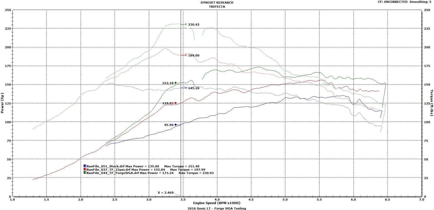
Versus the OE WGA, we gained another 17WHP, and a whopping 33WTQ! The torque gains are so impressive because this engine can really utilize boost levels higher than 22psi at the low to mid RPM range. Choosing some key RPM points, the following table summarizes the gains that were possible with just tuning and the Forge WGA:
|
|
3500 RPM |
5500 RPM |
6000 RPM |
6300 RPM |
|
OE WGA / Calibration |
146WTQ |
133WHP |
123WHP |
115WHP |
|
OE WGA / TRIFECTA (22psi) |
190WTQ(+44) |
155WHP(+22) |
143WHP(+20) |
141WHP(+26) |
|
Forge WGA / TRIFECTA |
229WTQ(+39/+83 total) |
166WHP(+11/+33 total) |
157WHP(+13/+33 total) |
156WHP(+15/+41 total) |
More than just Power
Believe it or not, the vast majority of calibration work required to make the Forge WGA work correctly has nothing to do with getting the big power gains. Because the turbocharger response from the BCS was dramatically altered with the installation of this part, we needed to start from scratch in dialing in the BCS table and the other PID controller constructs. We've spent about a week of total time on the dyno with various LUJ/LUV vehicles just getting everything mapped correctly.
Without proper calibration work, people installing this sort of part are likely to have sporadic, or even common issues with “boost limp mode”. This is where the ECU detects that there's been an ongoing boost control problem for long enough that it shuts down the boost control system entirely. This results in a maximum boost level of about 12psi (or 5psi on the OE actuator) and a very powerless vehicle!
- TRIFECTA Performance

Recommended Comments
Join the conversation
You can post now and register later. If you have an account, sign in now to post with your account.