


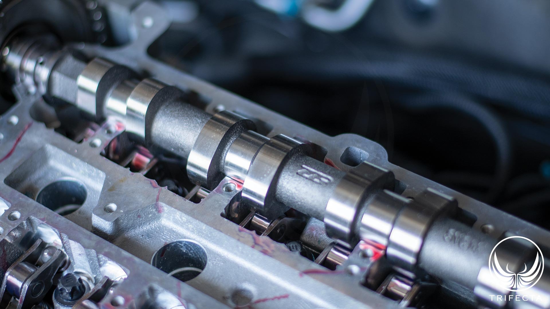
Figure 1 - ZZP Stage 1 intake cam
Background on “cam” modifications
Four cycle internal combustion engines (like the LUJ / LUV) follow a surprisingly simple concept. They are essentially a large air pump. The pistons descending the cylinder create a low-pressure area in the cylinder in which a mixture of air and fuel is drawn into. The mixture is compressed, and then ignited by the spark plug, sending the piston down the cylinder, generating horsepower. The cycle ends with the piston traveling back up the cylinder and pushing the exhaust products out of the engine in preparation for the intake of a new air / fuel charge.
The camshafts are an important tuning element of these kinds of engines. The camshaft design controls at what point the valve opens, how much it opens (this is lift), and when it closes (indirectly controlling the duration for which it is open). A camshaft rotates at half the speed of the crankshaft, so one rotation of the camshaft represents the entire 4 cycles of the engine (two rotations of the crankshaft).
When people talk about camshaft modifications, the most common terms you hear are lift and duration. However, there are other aspects as well, such as valve event timing – e.g., WHEN the valve opens, and closes in relation to top dead center (TDC). Overlap is an important tuning characteristic as well – this is the amount of time that BOTH the exhaust valve is still open (at the end of the exhaust stroke), and the intake valve is open (at the beginning of the intake stroke).
Camshaft basics, and configurations
The camshaft generally starts off as a forged metal shaft, which is machined to have lobes which transmit the lifting motion to the valve through a variety of different designs. The earliest “cam in block” designs, (which most GM V8 engines continue to use to this day) utilized lifters which ride on the cam lobe. These lifters would transit lift to the pushrod, which extended up into the valvetrain area, pushing a rocker arm up, which in turn would push the valve open. This is the OHV, or overhead valve configuration.
Eventually engine designers realized there are certain benefits to moving the camshafts from the engine block, up to the cylinder head. Here, the camshaft – or camshafts (more on this in a moment) are in the cylinder head itself as opposed to the cylinder block. There are far fewer moving parts, since the camshaft lifters can directly activate a rocker arm, or in even newer designs, the follower is essentially a rocker arm that rides directly on the camshaft, eliminating the need for lifters. This is the OHC, or overhead camshaft configuration.
Later, engine designers recognized the benefit of being able to dynamically adjust the timing of the camshaft related to the crankshaft while the engine is running. This is because what generally helps an engine make good low RPM power (torque) is detrimental at higher RPM (horsepower). When an engine is at lower RPM, you typically want the intake and exhaust valve events to happen closer to top dead center (TDC), and as the RPM rises, you typically want the events to happen later. The earliest camshaft phasing designs were able to adjust the camshaft timing on the fly to extend and optimize the power band, which was particularly useful on small displacement engines.
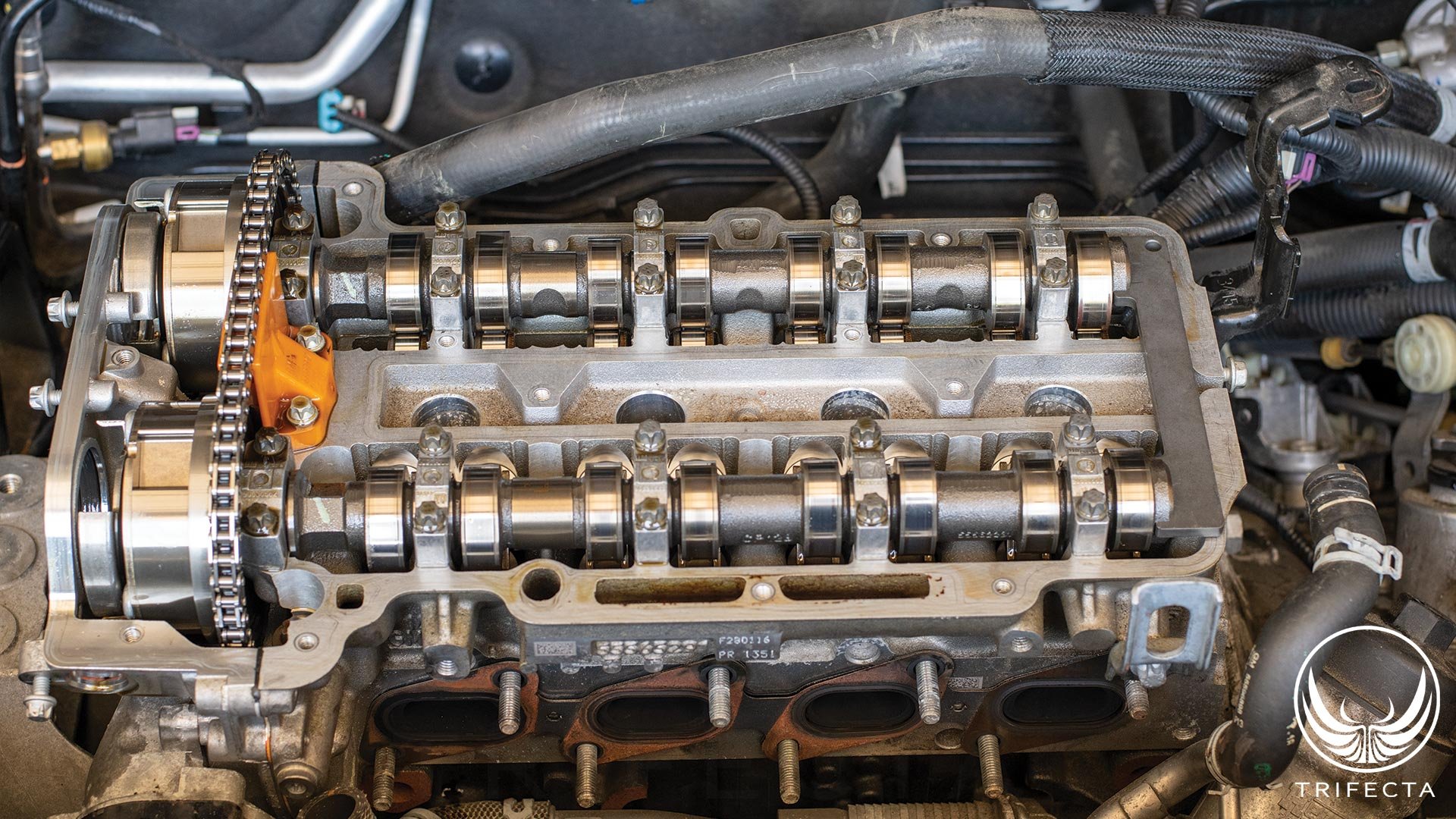
Figure 2 - DOHC configuration
As time went on, and technology improved, engine designs eventually incorporated two separate camshafts – one for the intake valves, and one for the exhaust valves – and independent phasing capability on each camshaft. Here, not only can the timing of the intake and exhaust valve event be adjusted on the fly, but also in relation to each other. Put another way, independent phasing authority on the intake cam and the exhaust cam allows valve overlap to be adjusted as well. This is the DOHC, or dual overhead camshaft configuration.
There have been even more technology improvements, such as variable lift technology, which is used on the newest GM 2.0L turbo engine (the LSY), but these technologies don’t exist on the LUJ / LUV, so we won’t discuss them here.
Making more power with cam upgrades
Generally speaking, when someone says they have “bigger cam(s)”, what they mean is they’ve replaced the original camshaft(s) with camshaft(s) that offer higher lift and more duration. That’s precisely what the ZZP Stage 1 cam kit does for the LUJ / LUV.
Why does this improve power? Higher lift means the valve opens further. By opening further, air /fuel mixture can flow into the cylinder more easily, just as the exhaust can flow out more easily. A valve that opens further presents less of a restriction. Longer duration means there’s more time for the air / fuel mixture to enter the cylinder and exhaust to exit.
The ZZP Stage 1 cam kit increases both lift and duration on both the intake and exhaust side, but how they did it was quite innovative.
The ZZP Stage 1 cam upgrade kit for the LUJ / LUV
At the time of writing, for $349.99 you could purchase the Stage 1 cam upgrade kit from ZZP. However, they also require upgraded valve springs and recommend upgraded retainers as well ($399.99).
When we purchased our kit from ZZP, we asked them to (which they gladly did) pre-assemble the valve springs and retainers on a brand-new cylinder head as we wanted to be able to swap back out to the OE cylinder head and springs at any point in the future for development.
Now, for the cam kit itself! It’s only one camshaft! But you’re thinking, “Wait a minute, didn’t you say this is a double overhead camshaft (DOHC) engine??”
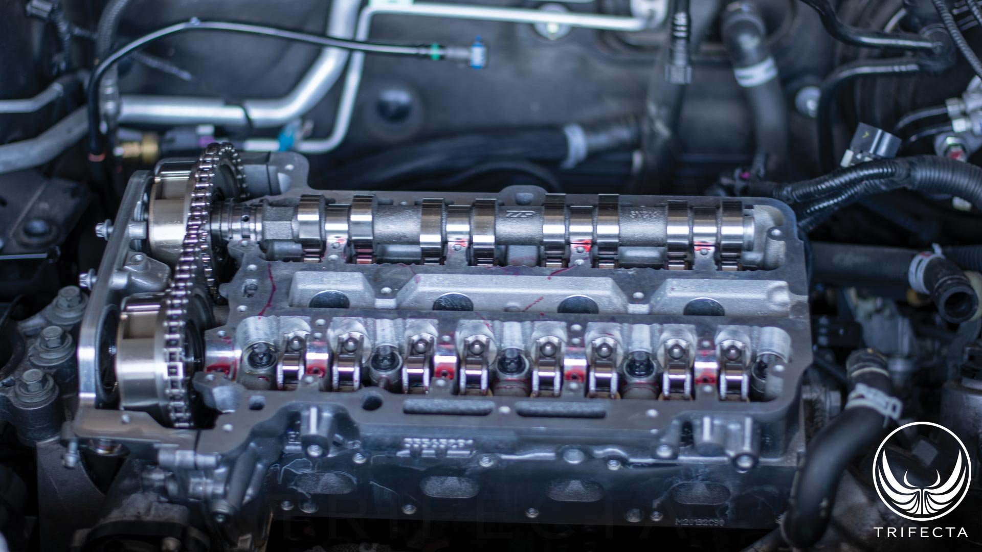
Figure 3 - ZZP Stage 1 Intake cam installed
What ZZP has done here is quite impressive. They determined that the intake and the exhaust camshaft come from the same core, and, hence, are interchangeable. They give you a new custom ground camshaft to replace the intake camshaft, and have you move the original intake camshaft in place of the exhaust camshaft!
Now, how on Earth does THAT work? The exhaust valve events are on a totally different timing than intake valve events! The secret is they provide a special tool that adjusts the position of what was formerly the intake cam, to properly actuate the exhaust valves!
Installing the kit
Our installation, admittedly, was a bit more involved than just swapping the cams, because we were swapping the entire cylinder head – though if you were installing the valve springs as well, you might have had to pull the cylinder head anyway. The cylinder head swap itself was straightforward, and we were singing praise to the engine designers that made it such that you can remove and replace the cylinder head without removing the front cover of the engine.
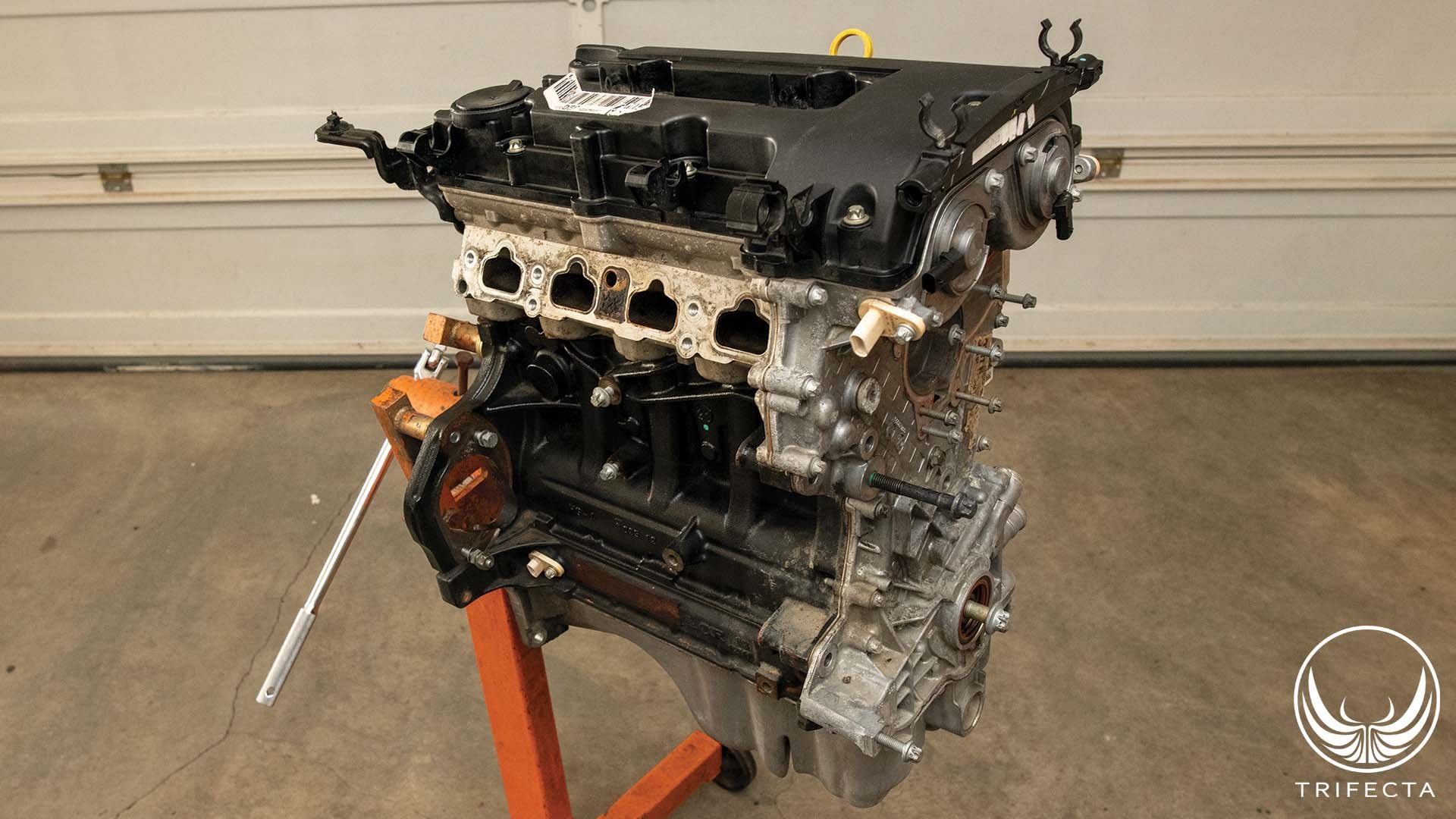
Figure 4 - Spare LUJ Engine
In order to time the camshafts correctly, in addition to the tool that ZZP supplies, you also need a special kit that includes several fixtures to hold the camshafts in place when the sprockets are reattached (and the crankshaft as well). We had a spare engine in our shop, so we were able to “practice” the camshaft installation and timing procedure several times before we performed it on our development vehicle.
The Development Vehicle
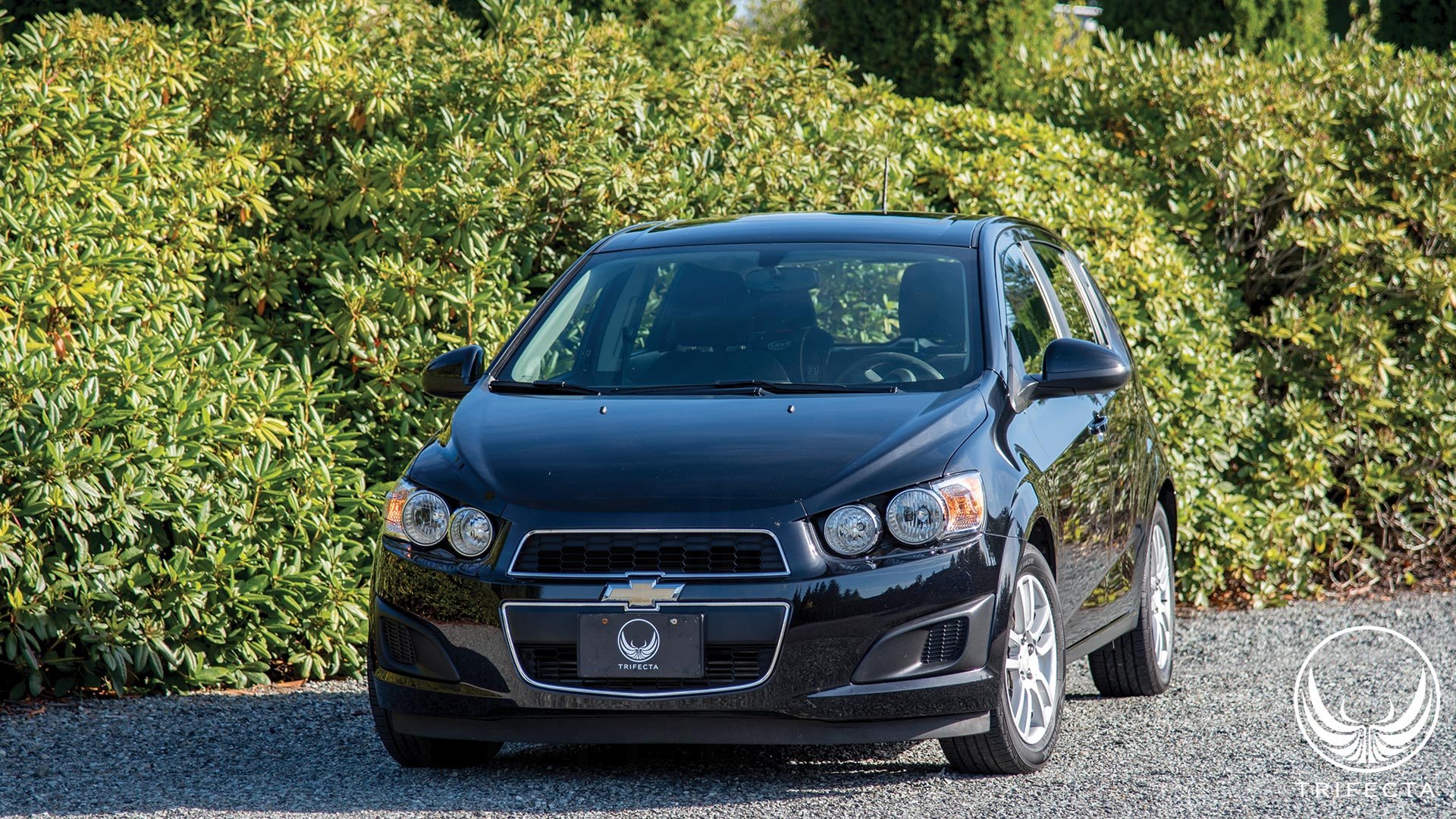
Figure 5 - TRIFECTA's 2016 Chevrolet Sonic Development Vehicle
When we develop calibration support for new parts, we aim to do so initially with minimal other modifications (though later we add the parts that customers will have). This helps us build a higher quality calibration by removing other mods from the equation. As such, we used our 2016 Chevrolet Sonic LT with the following engine mods:
-
42# Bosch “green giant” fuel injectors
-
RacerX cold air intake
-
ZZP Stage 1 cam w/ springs and retainers
The vehicle also has aftermarket wheels, limited slip differential, upgraded clutch and light flywheel, but none of these modifications are pertinent to the engine calibration. We retained the stock turbo specifically to find out if there would be any power gains with the cams alone. We ended up being surprised on this point!
Problem: cold start challenges
One of the first things we noticed when we started our Sonic after the install was that the cold start manners were terrible. After digging into the engine design and calibration parameters, we discovered why. The first issue is that unlike some of GM’s other variable valve timing (VVT) engines, this engine’s “park” position for BOTH cams is fully advanced. Compared to other engines like the 2.0T, the exhaust cam park position is fully advanced, and the intake cam is fully retarded. This ensures that on cold start there is minimal valve overlap.
The original cams in this engine were ground such that even with both parked (fully advanced), there was a trivial amount of overlap such that the engine would cold start OK. However, the profile of the stage 1 cam kit is such that overlap is increased to the point where the engine doesn’t run smoothly with both cams in the parked position.
In understanding this phenomenon and how to solve it, we first need to discuss what valve event overlap is and how it affects the engine’s operation. Valve event overlap describes a situation where BOTH the intake valve and exhaust valve are open at the SAME time. The grind of these upgraded cams is such that for a given cam position versus the original cams, there is more overlap. This is because when you increase the lift, you must also increase the duration. Considering for optimal power, you can’t open the exhaust valve any sooner, and you can’t close the intake valve any later, what you end up with is an exhaust valve that closes later, and an intake valve that opens sooner. In other words, more overlap.
If you have too much overlap under low RPM and light load, the engine won’t run smoothly. In fact, overlap is generally what’s responsible for giving an engine a “cammed” sound – that irregular, choppy idle sound. Immediately after cold starting the engine, the software goes into a catalyst light off mode. Here, ignition timing is retarded, and there’s more overlap (recall the park position of both cams induces overlap). Too much overlap causes operational stability issues, however, and that’s exactly why the cold start manners are problematic.
Solution: cold start challenges
The savvy reader will muse, “Well, this is a VVT engine, why not change the cam position via software during cold starts?” The answer is: that’s exactly what we did to fix this, but there were a few challenges.
Cam phasers require oil pressure in order to operate, but oil pressure isn’t immediately available during a cold start of the engine. It takes a certain amount of engine run time for the oil pump to deliver pressurized oil to the cam phasers. Also, the amount of time this takes is dependent on the engine’s temperature as well (colder temperatures mean thicker oil which means more time is required to deliver oil to the cam phasers). The ECU software can delay cam phasing for up to 8 seconds depending on the engine temperature. We addressed the issue by retarding the intake cam by the number of degrees we calculated was added to the overlap by the grind of the cams.
Catalyst light off mode, however, starts immediately after the engine is started, so the engine would run very poorly for a short period of time until the cam phasing comes online. We addressed this issue by both increasing the duration of the catalyst light off, and by delaying its commanding of engine parameters that would cause it to run poorly with both cams in the park position. It remains to be seen whether cold start emissions are blown out of specification by doing this, but at least we were able to correct the problem, and still allow catalyst light off to run for its original duration.
Problem: turbo spool-up
One of the other issues we noticed immediately was the turbo spool was dramatically worsened with the cams. This is not entirely unexpected in that the grind of these cams is designed to shift the power band upwards. The cause of the loss, however, was the ECU software was exiting scavenging mode too quickly (at too low of an engine RPM).
Scavenging mode on a turbocharged engine like this one is basically the equivalent of turbo spool mode. Here, the ECU software commands maximum valve overlap by fully advancing the intake cam and fully retarding the exhaust cam. This lets more of the boosted intake charge just sort of “blow through” the engine, into the turbocharger, quickly accelerating the turbine speed, and, hence, the compressor speed. As the turbocharger approaches full speed, the ECU software reduces overlap to improve power output.
The original scavenging mode parameters cut off the mode at much too low of an RPM, thus negatively affecting turbo spool up.
Solution: turbo spool-up
Once again, we went to work on the ECU calibration side of things to determine what we could do to fix the spool issues. While it might have been possible to simply modify the main cam phasing tables, we didn’t want to take this approach because we might end up in a situation where we’re at lower RPM, but the turbine is already at full speed. If there is too much overlap under this situation it can, at best cause loss of power, and at worst cause the engine to misfire.
So, we put our focus on the scavenging mode itself. It turns out there are myriad parameters that affect how and when this mode comes on. Our main challenge was extending scavenging mode from a maximum of around 3000 RPM to closer to 4500 RPM. A secondary challenge was retaining power enrichment mode activation WITH scavenging mode – something that wasn’t considered at the time this ECU software was written (though, interestingly, it was added later for the twin turbo V6 engine).
Driving Impressions
With our completed calibration in place, vehicle manners were largely original. The idle is every bit as smooth as it was from the factory thanks to our work in the cam phasing tables. As mentioned above, the cams have more overlap ground into them than the OE cams, so consequently, to maintain the smooth OE quality idle, the phasing settings for idle mode needed adjusting.
Once you get underway, the vehicle sounds “throatier”. There’s more of a growl from the intake thanks to the increased airflow the cams provide. Put the pedal down, and the engine easily revs out to 6500 – 7000 RPM with confidence. Peak power band is moved upwards, noticeably, and really puts you back in your seat once you hit around 5400 RPM.
All about the boost
That’s the burning question, right? What happened to the boost levels with the cams, considering all else is essentially stock?
The answer may be surprising: observed boost levels decreased, however, airflow levels increased! Let’s analyze this a bit further. First, what is boost? Boost is the amount of pressure in the intake system, between the turbocharger compressor outlet and the intake valves. It’s a measure of how much air is packed into the intake stream that has yet to be consumed by the engine.
It’s a common misconception to equate boost with power output. They are distinct concepts, yet they are related to some degree as well. If an engine produces 100HP at 15psi boost, then it should produce 200HP at 30psi boost, and 300HP at 45psi boost, right? This is incorrect for several reasons.
First, according to ideal gas law, as you increase the boost pressure, you’re also increasing the temperature of the incoming air. Unless you also increase the performance of your charge air cooler (intercooler), you’re sending hotter air into the engine as you raise boost levels. Hotter air is less dense, and if you overrun the capability of your charge air cooler, you’ll lose performance as boost levels go higher.
Second, the turbocharger’s efficiency itself is determined by things like the pressure ratio it runs at, versus airflow. Pressure ratio is the measure of the air pressure at the compressor inlet (which is near atmospheric pressure), versus the pressure at the compressor outlet. There’s a certain “sweet spot” for each turbocharger, and as you increase the pressure ratio (boost), you get further away from the sweet spot, and efficiency goes down.
Finally, the engine’s mechanical design itself may impose limits on incoming air pressure. An engine has a mechanical compression ratio. If we say an engine has a 10:1 compression ratio, it means the incoming air charge is compressed down to 1/10th of its original volume before it is ignited by the spark plug. If you send an air / fuel charge into the cylinder at 45psi as opposed to 15psi, you may exceed the design limit of the piston, rod, crankshaft, or even head gasket.
Let’s go back to the discussion about the cams and how they’ve lowered boost levels, but increased airflow. Remember the net effect of these camshafts is they allow more air to flow into the cylinder via increase valve lift, but also additional time because the duration is longer. Instead of packing the intake tract full of air, there’s more time for this air to move from the intact tract into the combustion chamber. The turbocharger is still moving the same amount of air, but the pressure is now lower. In actuality, airflow rates, as measured by the mass air flow sensor show an increase of airflow (which is a better measure of power output than boost level)! This can be explained by the turbocharger operating in a more efficient area of the compressor map due to lowered pressure ratio.
Hence, by the data, even with the stock turbocharger, we see less boost, but more airflow, and improved efficiency. How does this translate to actual power gains?
Performance Increases
At the time of writing, ZZP’s marketing material recommends only using this cam upgrade kit with an upgraded turbocharger (like their V3 upgrade). While we will eventually develop a calibration for the V3 turbo with their cam upgrade kit, and, in addition to developing a specific calibration for the cam upgrade kit, we wanted to find out what effect the cam upgrade kit alone would have on the power output, so we went to the dyno.
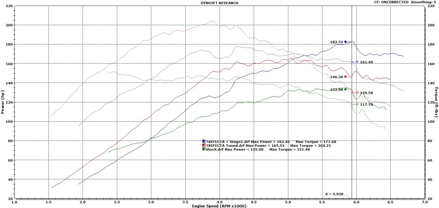
The results were interesting, to say the least! Above is a dyno sheet showing a comparison between our vehicle on the OE calibration, our vehicle on the TRIFECTA calibration with all stock parts, and our vehicle on the TRIFECTA calibration plus the cam upgrade kit. As can be seen here, the cam upgrade shifted the RPM band upward by about 500 RPM, but also caused a loss of peak torque, for the same reason.
Let’s start our analysis with the horsepower numbers. Peak HP on the OE calibration is at 135HP @ 5850 RPM, as measured by the dyno roller. Peak HP on the TRIFECTA calibration / OE hardware is 165.52HP @ 5053 RPM, and, peak HP on the TRIFECTA calibration with cam upgrade kit is 182.44HP @ 5950 RPM. Peak to peak, this is a gain of just under 17HP from the cams by themselves (comparison of the TRIFECTA calibration on OE hardware vs TRIFECTA calibration with the cam upgrade kit), and a total gain of 47HP from when the vehicle was manufactured.
Now, let’s look at the torque. Peak torque on the OE calibration is at 150 lb-ft @ 2500 RPM. Peak torque on the TRIFECTA calibration / OE hardware is 204 lb-ft @ 3880 RPM. Finally, peak torque with the TRIFECTA calibration and the cam upgrade kit is 178 lb-ft @ 4250 RPM. Peak to peak, the cam upgrade kit caused a loss of 26 lb-ft of torque, however, there was a gain of 28 lb-ft of torque over stock.
At the time of writing, our calibration was still in the “beta” phase, and we still have some aspects of the calibration to sort out. One issue we ran into was mechanical noise being picked up by the knock sensor at high RPM. Note in the dyno sheet, the power level drops dramatically after 6000 RPM – this is due to false knock being detected. We also see opportunities to improve the calibration in the 4000 RPM range, where it transitions out of scavenging mode.
Conclusion
Overall, this is a relatively low-cost upgrade for your engine that has proven results. For people with a long-term plan to mod their 1.4T vehicle, this is certainly a “build for the future” sort of modification. At some point, you will want upgraded valve springs, and especially if you are running, or plan to run an upgraded turbocharger like the V3, the cam upgrade kit is a great choice. Our work has proven there are measurable gains in horsepower even on the stock turbocharger.
We believe the cams will really shine with the V3 turbocharger and look forward to developing the calibration for the V3 + cams. Our work with the V3 has shown that its potential is boost limited – that is, we have found that no matter how hard you try to run the turbo, the manifold pressure won’t rise past a certain point. Because the cams lower the boost levels without sacrificing airflow, we believe we’ll be able to run the V3 faster and unlock some additional gains due to flow and efficiency improvements.
The current beta calibration for the cam upgrade kit is available now to all TRIFECTA Elite Calibration customers. Customers wishing to use our beta calibration should contact us via our support system on our site!

Recommended Comments
Join the conversation
You can post now and register later. If you have an account, sign in now to post with your account.